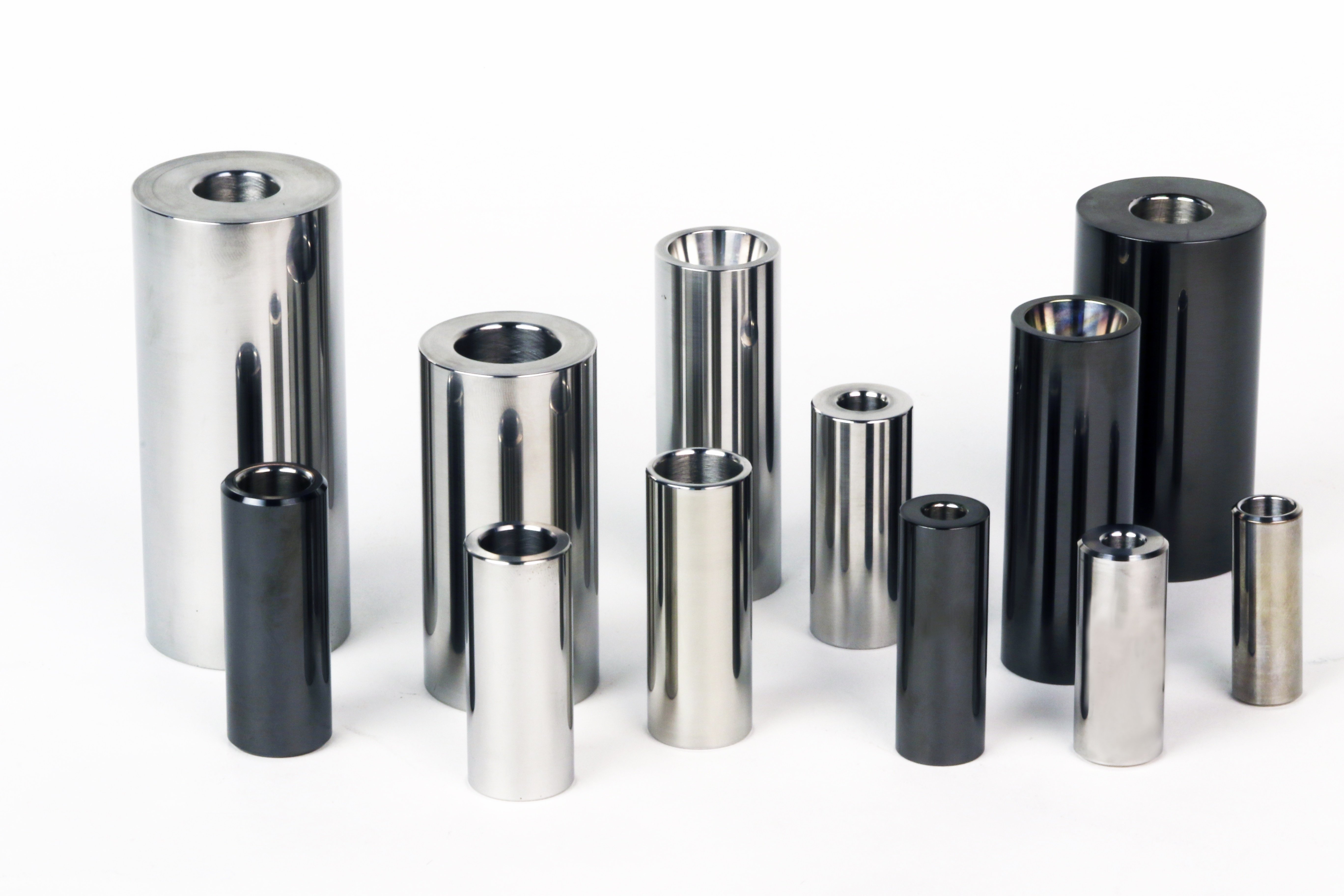
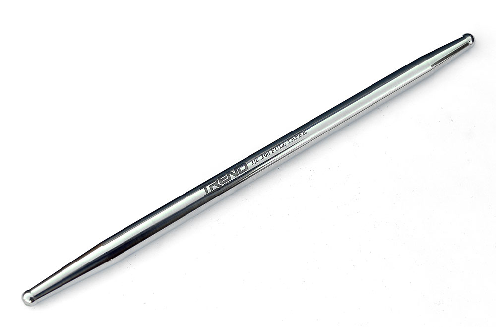
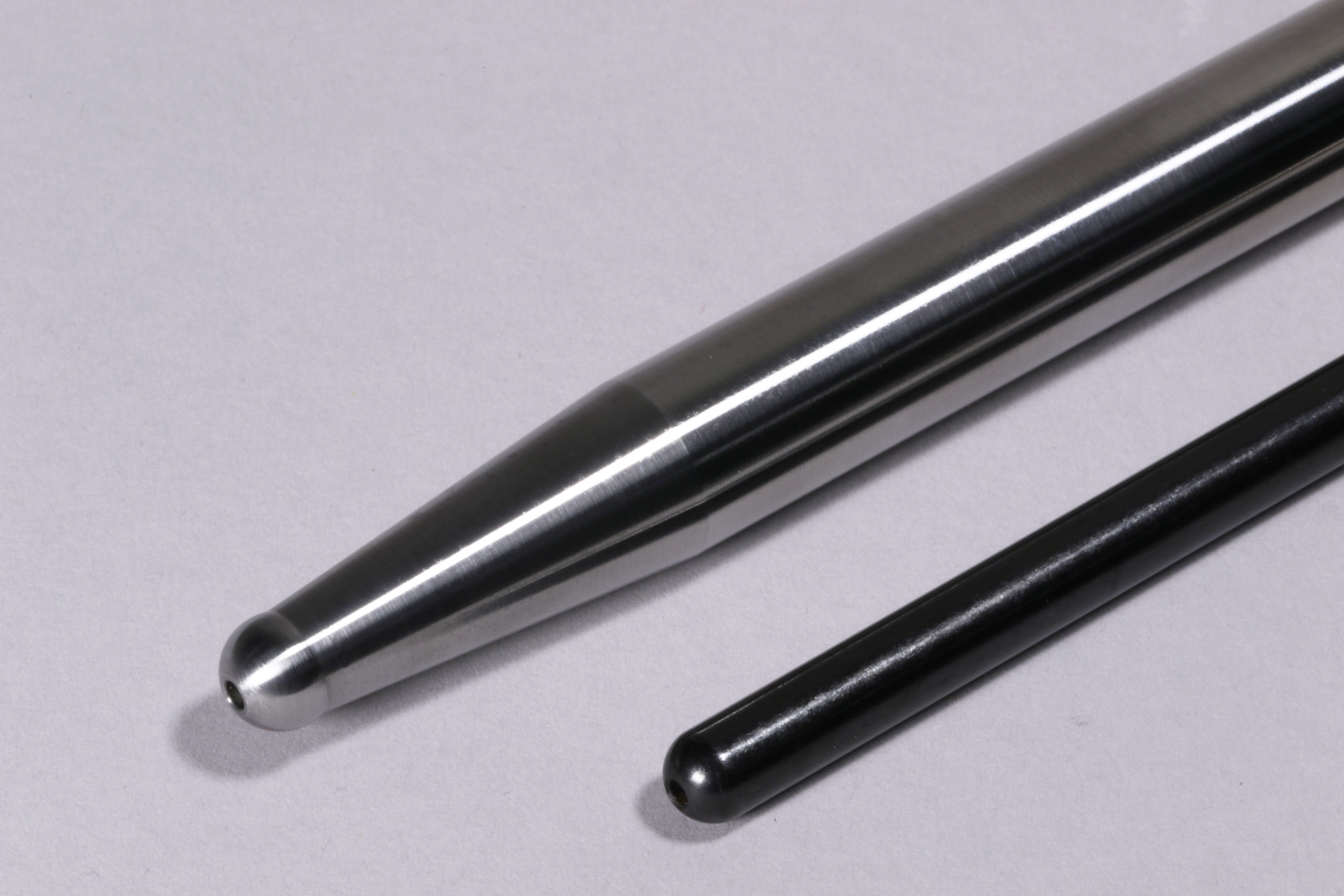
Tapering is an evolution in pushrod design that maximizes overall strength, clearance, and valvetrain harmonics.
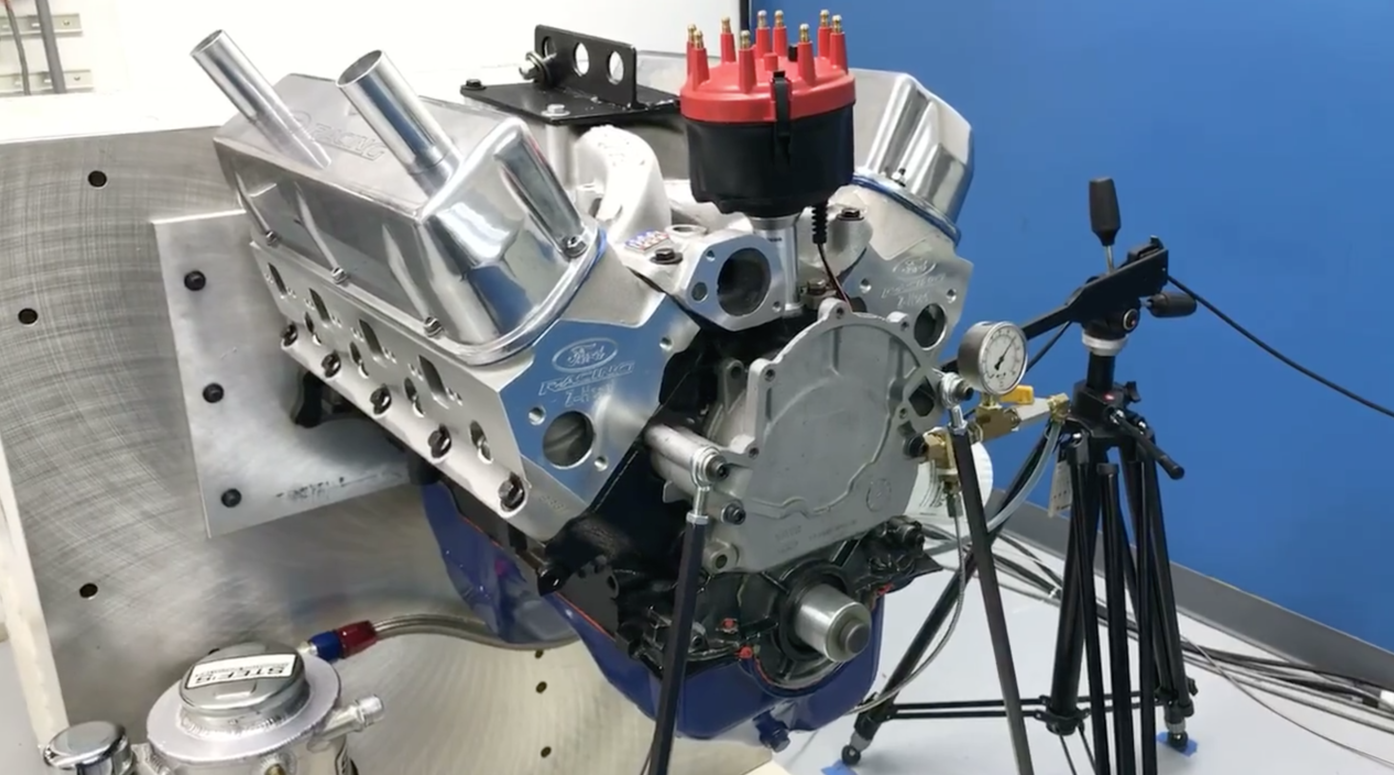
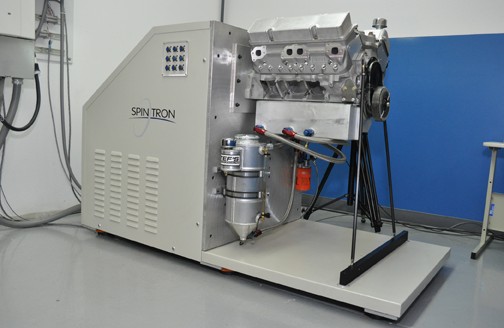
At some point in the decades old escalation of power, straight pushrods became problematic, even those that were hardened for performance use. Bigger cams, higher spring pressures and associated harmonics increased pushrod failure rates. The initial remedy was thicker-walled pushrods to resist rising spring pressure and more aggressive camshaft action. Finally, manufacturers began to seriously investigate the dynamics of pushrod action and understand the forces and loading a pushrod endures. In 1993 Trend Performance owner Bob Fox invented the Spintron; a simple yet effective machine capable of testing a valvetrain at very high rpm. Fox built his machine to test and improve his company’s high-performance pushrods, but it soon revolutionized racing engine performance.
Spintrons helped designers observe and confirm the physics behind pushrod motion and quantify the loading and attending frequencies that affect a pushrod in much the same way as a tuning fork. As these forces became clearer, designers advanced solutions to accommodate the strength and force requirements within the available real estate adjacent to the pushrod along it’s travel; most typically the nearby port wall. In the simplest of terms tapered pushrods evolved because they offered a means of increasing pushrod diameter and strength according to available space while still limiting its size where it needed to function near fixed obstacles.
A tapered pushrod splits the difference in strength between a small diameter pushrod and a large diameter pushrod while retaining its ability to function properly in limited space. A tenant of column theory states that a tapered column (like a flagpole) will never be any stronger than a straight column whose size is equivalent to the maximum diameter of the taper. But taper does increase the strength beyond that available in straight column of lesser diameter and further, it can be biased in an advantageous direction to suit the needs of the application.
In effect, taper allows you to run a larger, stronger pushrod in the same confined space without penalty. It goes almost without saying that flex in a pushrod initiates inconsistent valve timing and can lead to a buckling failure after many cycles. Because lash clearance provides a brief relaxed state, it essentially turns the pushrod loose on each cycle. So, it goes from no load to maximum load very quickly with maximum load occurring near peak lift where maximum spring pressure is exerted.
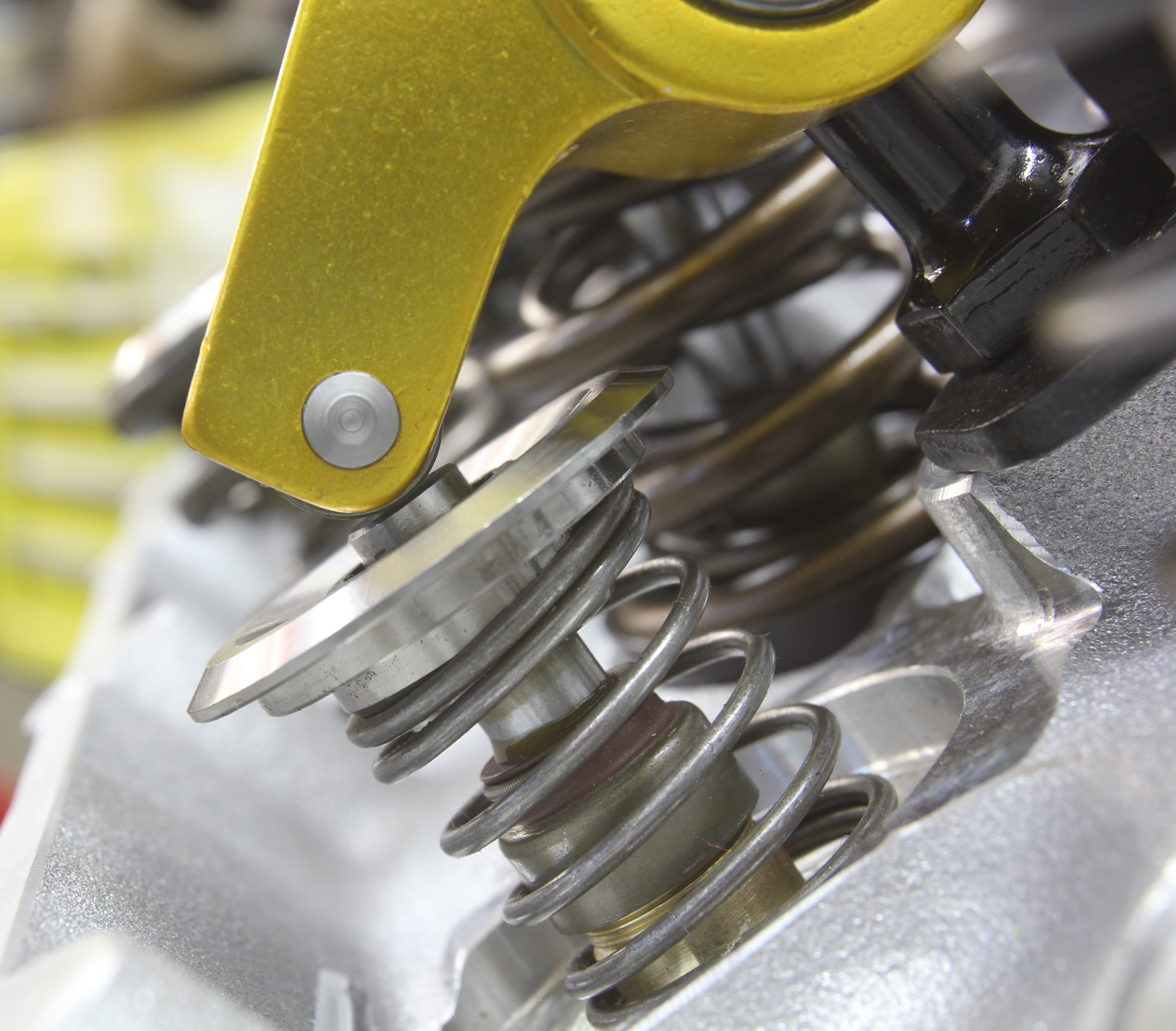
In most engines the pushrods do not operate perfectly linear to valve lifter travel or the fixed arc of rocker arm motion. A vector is introduced to confound the forces acting on the pushrod. Conventional thinking suggests that compression force acting on the pushrod remains essentially straight while directing non-linear side force against the lifter cup or the rocker arm adjuster ball or cup as it may be. Depending on the angularity a pushrod may be forcing the lifter against one side of its bore by an amount that can be calculated. And the same can be said at the rocker arm as well.
Combined with the recurring relaxation per cycle and rapidity of cycle loading, the pushrod will vibrate according to its natural frequency determined by diameter, length and wall thickness. And that’s not accounting for the column of oil circulating through the pushrod which also adds mass and may act to some degree as a damper.
Through diligent Spintron investigation designers identified the dynamics and methodologies of tuning pushrods to suit varying requirements relative to engine speed, camshaft action, and spring loading to essentially calm the valvetrain into a more effective state. The cure often differs from the intake to the exhaust because the system is opening an intake valve to relatively low pressure while the pushrod must also overcome the higher cylinder pressure present in the chamber prior to cracking open the exhaust valve. So, the exhaust side is always working harder and under higher stress. The increased forces on the exhaust side are multiplied by the area of the exhaust valve and transmit back through the valvetrain where the pushrod is often the weakest link.
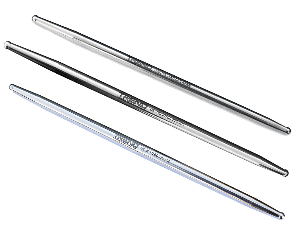
With tapered pushrods the harmonics are often less because the changing cross sections helps to dampen them. But, in most cases a pushrod is still an eccentrically loaded column During the lift-cycle, the pushrod is essentially pushing in different directions at the same time: up and to the side and down and to the opposite side. The rising lifter and the arcing rocker arm vary the vector through the range of travel. When the opposing sides finally resist, the pushrod buckles and drama ensues. The key then, is to incorporate a single or offset dual tapered pushrod of the largest diameter the surroundings will permit.
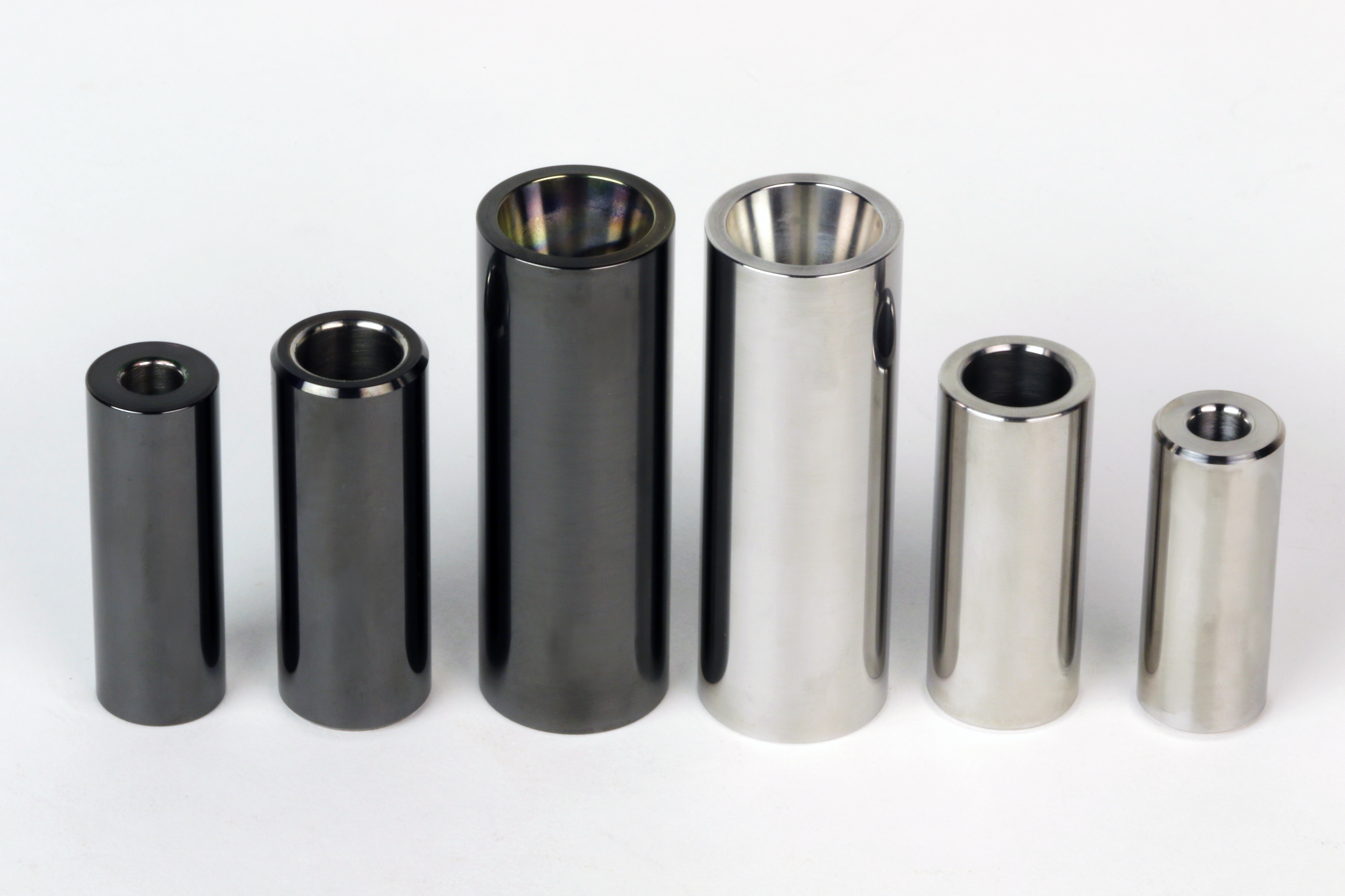
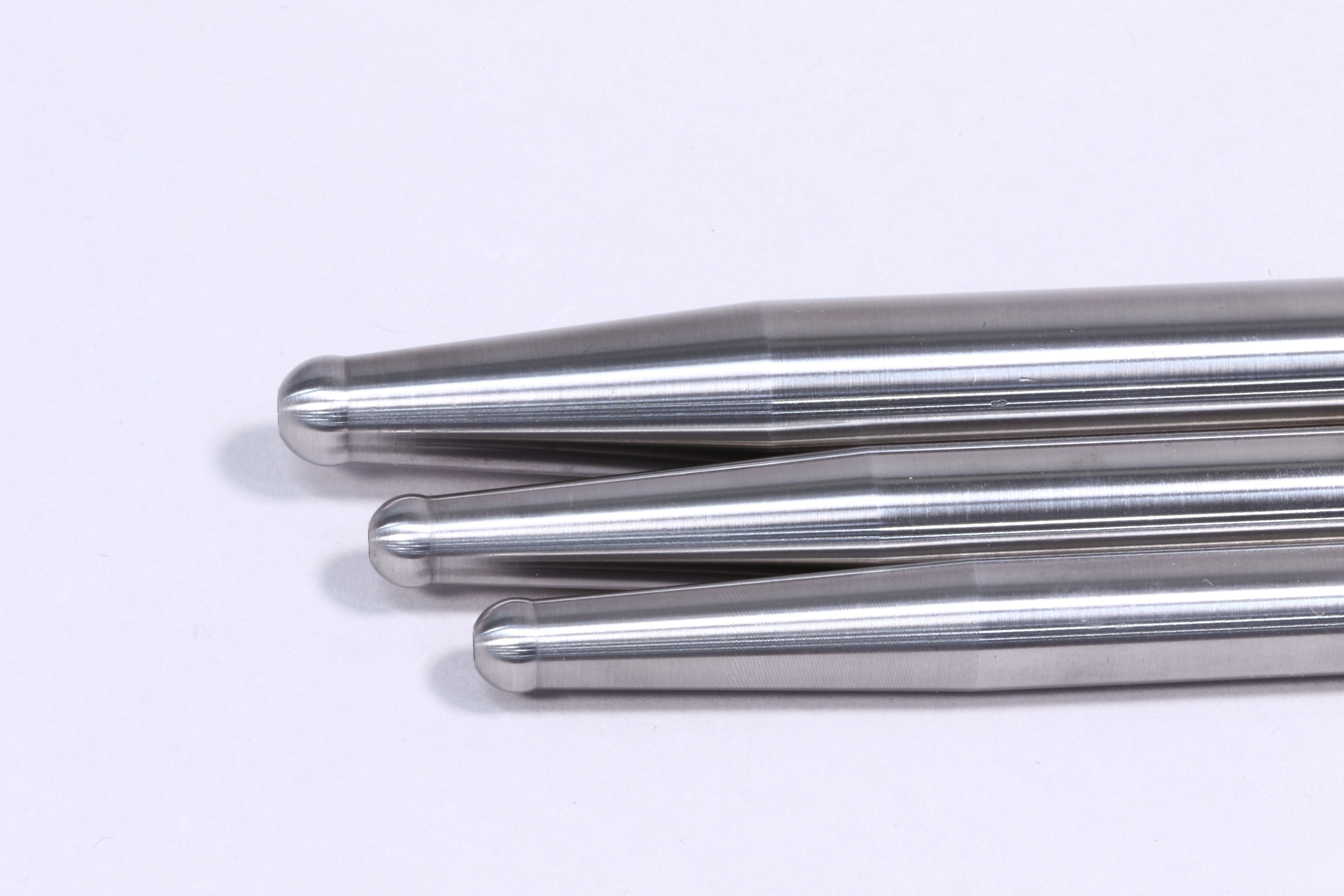
Taper helps lessen angular-induced deflection by positioning the greater mass and diameter closer to the energy source which is the lifter. Designers can tune this by determining where to place the maximum diameter and how much taper to apply. So, tapered pushrods are highly beneficial in almost every application that suffers from valvetrain instability. The slight penalty in mass is easily overcome by the improvement in valve control particularly as it relates to spring surge and valve bounce on the seat. The pushrod functions on the slower moving side of the valvetrain relative to the valve so a small increase in weight does not affect spring function to any great degree.
Tapered pushrods help dampen harmonics in the valve train. Designers take great pains to ensure that the pushrods natural frequency falls outside of the engine’s operating range so that it doesn’t transmit a surge dynamic to the valve springs. Compression and angular deflection are the two primary concerns for pushrod engineers. Engines that are equipped with roller lifters, high rocker ratios and very heavy springs operating at high engine speed will always benefit from tapered pushrods with the primary mass biased to the lifter end where acceleration is high, and you need to keep the lifter in contact with the cam lobe.
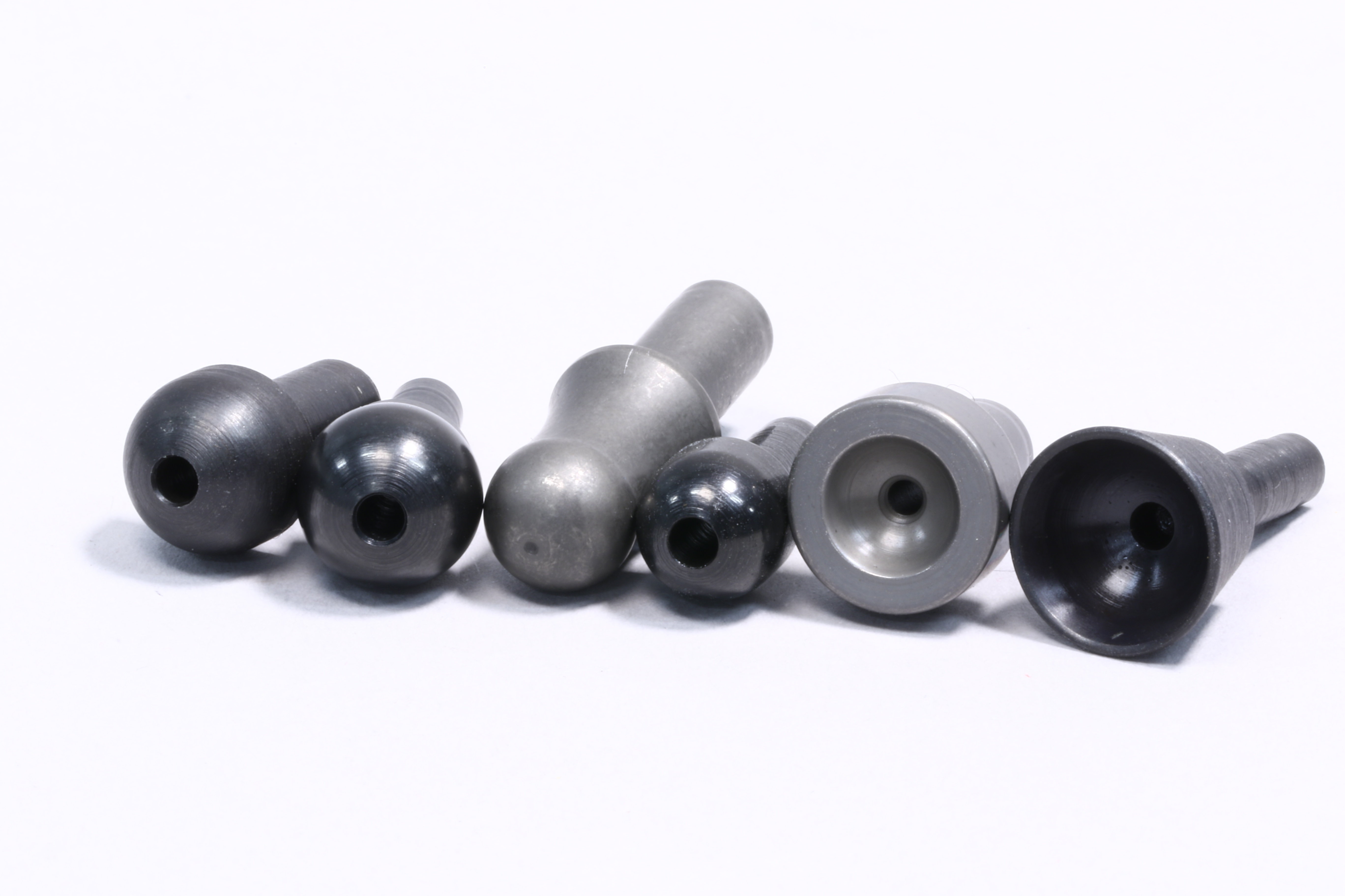
Because of the angularity issues, it is very important to ensure maximum compatibility between the pushrod tips and their corresponding seats or cups. The radii must match, and ball tips must incorporate additional freedom of movement, up to 270 degrees to avoid binding. Most pushrods in this environment are made of 4130 or 4140 Chromoly steel in thicknesses from .080-inch to .120-inch to maximize strength. Almost all high-horsepower engines use some type of tapered pushrod except perhaps those special designs where the ports are configured to permit very large diameter straight pushrods that are shorter and stiffer as found in contemporary Pro Stock and Pro Mod motors.
In today’s camshaft designs where 1-inch or greater cams have become almost normal, pushrod integrity and alignment have become more critical than ever. In many cases, these engines also incorporate severely offset lifter cups to reposition the pushrod for better clearances. Manufacturers report few issues from this, but again, it depends on the direction and degree of offset in terms of how much side loading the lifter sees under pressure. In part, guided lifters were developed to help maintain alignment and mitigate the rapidly changing stress environment in these applications.
Your pushrod selection is far more critical than just acquiring the right length for proper rocker geometry. Trend’s support line can help you toward the best selection if you can provide the details about your combination that will let them make a proper recommendation. Every case is different, but Trend has the engineering and range of assets to outfit your engine with the optimum pushrod configuration for your engine, no matter how unique it might be.