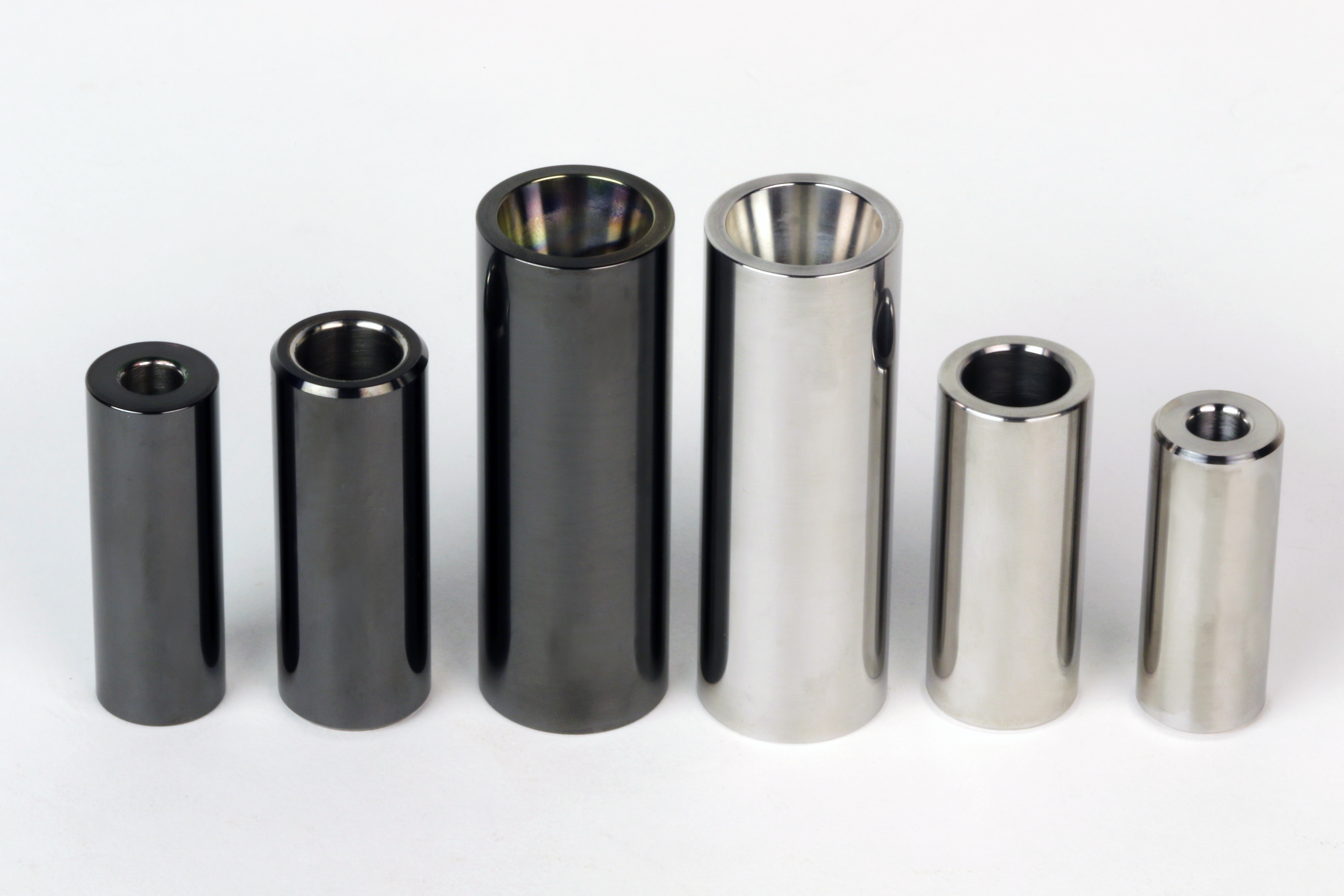
Flat tappet lifters still have home in racing circles around the world. And, while they may seem simple, their design and manufacture is anything but.
Valve actuation via tappets, cam followers or valve lifters has been the time-honored solution for most internal combustion engines. Some of the earliest versions were actually roller tappets because the idea made sense to early designers and it held promise to reduce friction and parasitic drag. These valve lifters were largely seen in early twentieth century aircraft engines and some high-end luxury automotive applications. But for the next eighty years, automotive powerplants survived and flourished with simple mechanical tappets that bore directly against the camshaft lobes with a lubricated metal to metal interface. They were simple, inexpensive and surprisingly reliable in most low to moderate speed applications.
As solid mechanical tappets gained acceptance, they evolved with radiused edges and in some cases, mushroom style lifters to gain a larger lifter face within a confined space. The cam lobes were ground with a taper to one side that encouraged lifter rotation to promote even wear.
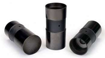
The bane of flat tappet lifters is, of course the break-in period where minimal lubrication and valve spring pressure conspire to flatten a cam and ruin lifters very quickly. Aggressive cam designs and valve spring pressures only exacerbate the problem so very careful break-in procedures are required. Special break-in oils with higher ZDDP content are recommended and the best procedure is to pre-oil the engine prior to firing so all the oil galleries are full. Following that, most builders take the engine immediately to 2500 rpm to ensure plenty of oil splash during the 20-30-minute break-in period.
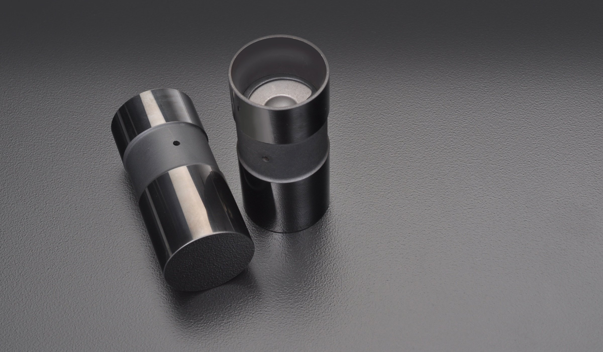
Typical flat tappet solid lifters are manufactured from hardened iron or chilled iron which is inexpensive and easy to machine. However, Trend's flat tappets are manufactured from tool steels which is much harder and stronger and allows the lifters to live in incredibly brutal racing environments. They are available in Cup, and Premium versions which are compatible with tool steel and cast iron camshafts respectively. In addition to strength and wear resistant characteristics, the properties of tool steel, and available DLC coatings, reduce friction which promotes power.
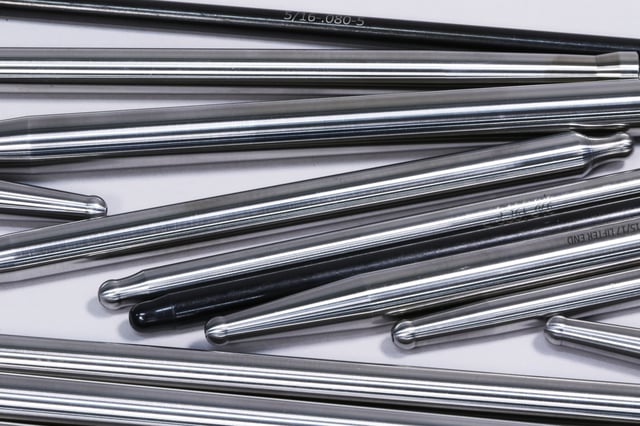
In lower class sportsman racing, older stock blocks are often prevalent. These blocks may have recycled through multiple rebuilds and cleanup honing without the benefit of close inspection and measurement. The lifter bores may be out of round or tapered due to lengthy service. And in many cases, they are not perfectly aligned to the camshaft lobes. So, issues unrelated to lifter quality conspire to promote failures. Lifters can cock in the bore, creating friction and galling and misalignment with the cam lobes virtually ensures early failure. Sleeving and realigning lifter bores as done in most race engines is not generally an option in sportsman classes.
Critical Features Affecting Flat Tappet Lifters
Tappet Rotation:
Flat tappets are designed to rotate in their bores to equalize and minimize wear. Rotation is driven by offsetting the lifter bore from the center of the lobe face with lobe taper in the same direction as lifter offset. If a flat tappet does not rotate continuously to cycle the contact face with the cam lobe, it will quickly fail.
Tappet Crown:
A very slight spherical crown ground on the faces of flat tappet lifters prevents the edge of the tappets from riding off the edge of tapered cam lobes. This works in conjunction with lobe taper to promote tappet rotation. Tappet crown is typically specified by the amount of lobe taper determined by the engine manufacturer. Normal tappet wear occurs as a “donut” partway off-centered on the face. Wear near the edge indicates a tappet with too little crown for that cam. Loss of specified tappet crown indicates a worn cam.
Lobe Taper
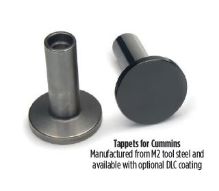
Lobe taper is a very minute amount that one side of a flat-tappet cam lobe is ground smaller than the other. Flat tappet cams typically have taper left or taper right with zero to .003-inches taper, depending on the engine type and the specified direction of lifter rotation. Camshaft lobe taper works in conjunction with the tappet crown and tappet bores offset from the cam lobes to drive flat tappets into rotation within their respective bores. This is done to ensure optimum wear characteristics.
The direction and amount of lobe taper is measured across the diameter of the base circle. Looking at a camshaft with the front to your left, you can define lobe taper as follows. If the forward (left) side of the lobe is larger, the lobe is ground with taper-left. If the rear (right) side of the lobe is larger, the lobe has taper-right. All lobes will have the same amount of taper, but not always the same direction. Taper right pushes the cam into the block via angled pressure from the rotating tappets. Taper-left and mixed taper pushes a cam forward. This requires a cam thrust plate just like roller tappets.
Cup-Style Lifters
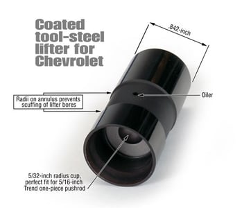
Manufacturing the best possible solid flat tappets takes a cue from NASCAR Cup racing where earlier regulations influenced most of the improvements made in solid flat tappet design. In the beginning, solid flat tappets were manufactured from hardened iron or chilled iron and operated on cast iron camshafts. Today these tappets are fashioned from fine tool steels like M2, finished with a durable DLC coating, and operate on tool steel camshafts with case-hardened lobes.
Two essential qualities, strength and resistance to wear, are the primary drivers of modern solid lifter manufacturing. These M2 tool steel qualities are reinforced via controlled heat-treating processes that include hardening to Rockwell 64. The lifters mirror-like status derives from precision grinding and lapping to a micro-polished finish. It is further supported by the use of DLC, diamond like coating to ensure the best possible surface quality.
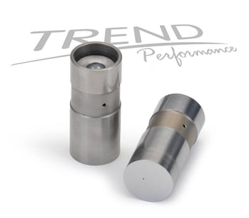
Direct Lobe Oiling
A popular feature in many applications where higher valve spring pressure are a factor, direct cam lobe oiling through the lifter provides great insurance against failure. This is accomplished via EDM or electrical discharge machining. A small .012-.015-inch hole is drilled in the lifter foot to provide a flow path for oil to pass through the lifter directly to the cam face. The hole is drilled with a powerful electrical discharge instead of using a fragile drill bit. By drilling the hole off center, a constant supply of fresh oil is supplied to ensure lifter and lobe integrity.
Flat Tappet Applications
Many local sportsman racing classes still mandate flat tappet lifters to help contain the cost of racing. They have remained a staple of low cost short track and dirt track racing series and particularly with “claimer” engines. As part of its ongoing support for regional sportsman racers, Trend Performance introduced a new series of uncoated tool steel flat tappet solid lifters for engines with low cost cast iron camshafts running 7,000rpm and higher with increased valve spring pressures. Introduced in 2011, these tappets surpass the performance of standard iron tappets because they can be re-used. Trend also provides a special service that resurfaces their contact area allowing indefinite longevity. These lifters incorporate the following performance features that all sportsman racers will appreciate.
- DLC coated for use with alloy steel and tool steel camshafts
- Super fine surface finish of 0.5Ra
- Tappet foot finish exceeds all current NASCAR requirements
- Hardened to 63-64 Rockwell
- 5/32in radius seat exactly matches curvature of 5/16in pushrod
- Radii on annulus helps prevent scuffing of the lifter bores
- Weigh less than 69 grams
- Durability tested with several Cup racing teams
- Direct replacement for Schubeck ceramic-foot lifter
- Ideal higher engine speeds (7,000rpm+) and higher spring pressures
- Available uncoated (Premium style) for use with cast iron camshafts
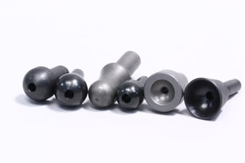
A place remains for solid lifers in various racing series that keep a lid on cost. The advances that make modern flat tappets a great deal incorporate tool steel materials, precision surface finishing and heat treatment, precision pushrod cups, DLC, diamond like carbon coating and EDM drilled oiling holes to validate a total performance package in what most people view as a simple low tech solid lifter. The underlying science is considerable. Trend’s lifters are far more precise than anything ever offed in a production environment. They solve all the exasperating problems associated with solid lifter use in racing and street applications.

