In this segment of Spintron Secrets, we dive into the concept of Valve float, the phenomena that cause it and a few valvetrain topics that can make or break a race engine. Rev on!
Let’s picture the scenario. The engine is running smoothly on the dyno but as the revs rise, maybe past 7,000rpm, the power suddenly drops and the airflow plunges. Or perhaps you’re out on track, and the motor hits an invisible wall, refusing to make more power.
In either case, the valvetrain could be out of control. In short, the valves – and in particular the intake valves – are hitting the seat hard and bouncing open again, perhaps multiple times.
This is valve bounce, the most damaging of several phenomena that collectively comprise valve float, which is when a valve’s opening and closing phases don’t match the cam lobe profile in the way that they should. At best, you’ll stop making power as the rpm rises. At worst, the valve will make contact with the piston, or it – or another element of the valvetrain – will break.

Ask the expert
For some insight into how valve bounce comes about, we turned to Bradley Brown, senior manager for innovation at Trend Performance. After studying at the NASCAR Technical Institute in Mooresville, NC, Brown spent several years at the Comp Performance Group, running valvetrain analysis testing and developing testing methods on the SpinTron machines that are produced by Trend Performance.
“People often think that valve float means that the parts are coming out of contact, but that’s not necessarily true,” he begins. “It’s actually a combination of valve bounce and valve loft. Valve loft is when the dynamic lift at high speed is higher than the measured static lift. Many times, the parts are actually still in contact. Valve bounce is when the valve opens again after closing and certainly means that the engine will not make power – and will break things.”
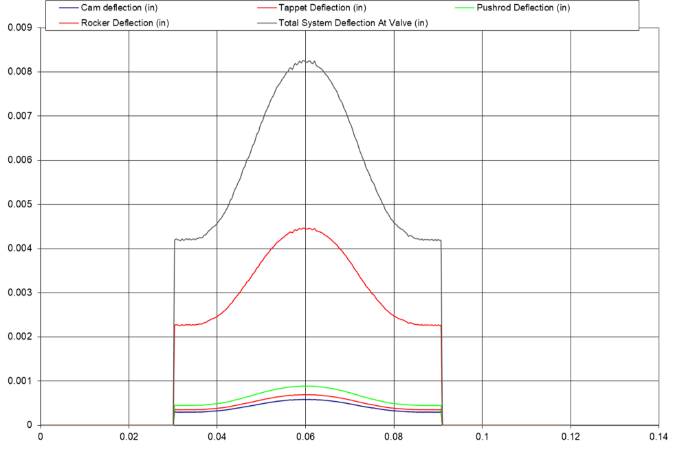
To help to get a handle on valve float behaviors, valvetrain test rigs like the SpinTron can precisely track the valve’s movement over time, resulting in a curve like the one in the example below.
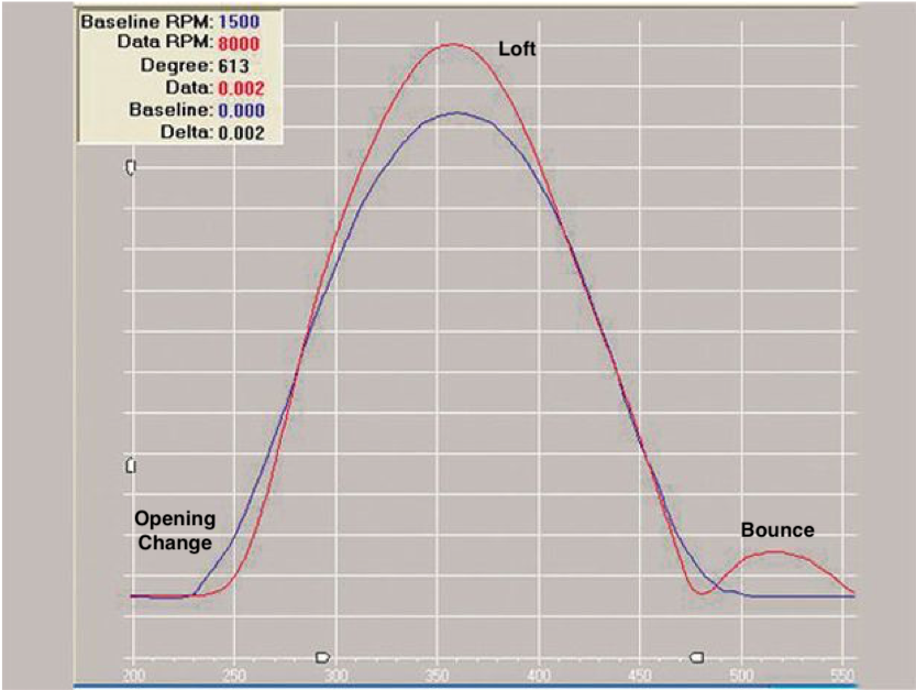
SpinTron measurements using the Laser Valve Tracking System (LVTS) usually begin with a baseline valve trace at a stable engine speed – perhaps 2,000-3,000rpm. This will generally show that the valve movement remains well controlled by the spring. The maximum lift is typically lower than its potential highest value due to the deflection of the rocker arm, pushrod and other components. A Harley-Davidson twin-cam, for example, has a lot of deflection in the system due to the comparatively long pushrods.
“You can get a lot of deflection on the opening side of the valve motion curve,” Brown explains. “All the parts have some deflection and in an overhead rocker system, the rocker can be up to 40 percent of the total deflection due to it being the only component that’s in bending where all other components like the pushrod are in compression.
“Energy is stored in the components [as they deflect] and is then let go as the cam acceleration slows down and the lifter comes ‘to the nose’ of the cam before everything turns around and goes in the other direction.”
As engine speeds rise, this can lead to valve loft. This is when the parts start to be ‘thrown’ as the cam acceleration comes off, early to mid-lift. The peak valve opening begins to match the theoretical maximum before deflection so there’s more airflow than at lower rpm. This increased valve lift and/or duration is sometimes deployed as a means of compensating for regulatory limits (rulebook imposed max lift) on how much lift the camshaft can provide. But when it closes, the valve is likely to impact the seat harder than normal – even if it is not bouncing out of contact with the seat, yet.
At even higher rpm, the extra energy in the system means that the smooth, controlled closing ramp that brings the valve closed is replaced by a sharper drop. In some cases, the valve is so light that it will outrun the spring, and seat before the coils can catch up with it. If the forces from the inelastic collision of the valve seating event are higher than the spring dynamic seat force at the moment when the valve is seating, the valve will hit the seat and bounce back open. This is especially critical for the intake valve, as the engine is trying to create cylinder pressure at this time.
How can we diagnose valve bounce?
Engine builders can use a SpinTron to analyze what’s going on when the valvetrain is out of control and test component options to mitigate valve bounce. These test rigs have been used since the early-1990s by leading players such as Hendrick Motorsports and TRD.
“The SpinTron is one of the only devices out there that enables you to clearly identify and quantify valve bounce, and where it’s happening,” says Brown. “The beauty of SpinTron is that if you drop a valve, it won’t hit a piston and blow up the entire bottom end. You just replace the valve and keep testing. Experienced operators can even detect a broken spring or a dropped valve just from very minute changes in sound.”
Whether an engine’s limit speed is identified by the driver on track, or by a SpinTron back at the shop, valve bounce issues will usually continue to worsen as the revs rise even higher. But as Brown points out, “sometimes people think they’re in a safe region of rpm but they’re actually living with something that’s just slightly bad. But if you do that for long enough, it’ll still break parts.”
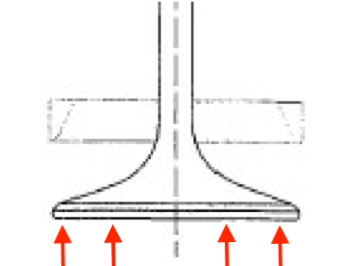
The severity of the bounce is affected by the shape of the valve head, the softness of the seat material and – most importantly – by the seating velocity. However, Brown advises that seat materials should be chosen primarily because of their wear properties and describes changing the material’s softness to solve bounce as “putting a band-aid on the problem that would most likely expose several others”.
Bounce tends to fail parts due to two major phenomena. One is the incredibly high forces during the sharp change in direction during a valve bounce. The other is related to the higher strain rate – the speed at which the forces are applied to the parts.
High strain rates are known to cause increased fatigue in materials. Higher seating velocity applies high-enough strain rates to the components for them to fail, even though they may be able to handle that same level of strain if it is applied in a slower, more controlled fashion.
Valve loft – the good and the bad
The issue is complicated by valve loft, another aspect of valve float that can have performance advantages if managed properly – but which can also signal a deterioration of control in the valvetrain. Valve bounce is usually associated with loft modes that have been intentionally or unintentionally introduced to an engine.
“Valve loft is controlled chaos,” assesses our expert. “An engineering standard for high-frequency vibrating systems is that the natural vibrating frequency of any component should be 25-times higher than the frequency of whatever’s driving it. It’s a safety factor to prevent resonance from becoming an issue in a system. But we’re nowhere near that with valve springs and engine rpm, where we’re only three or four-times higher in many cases.”
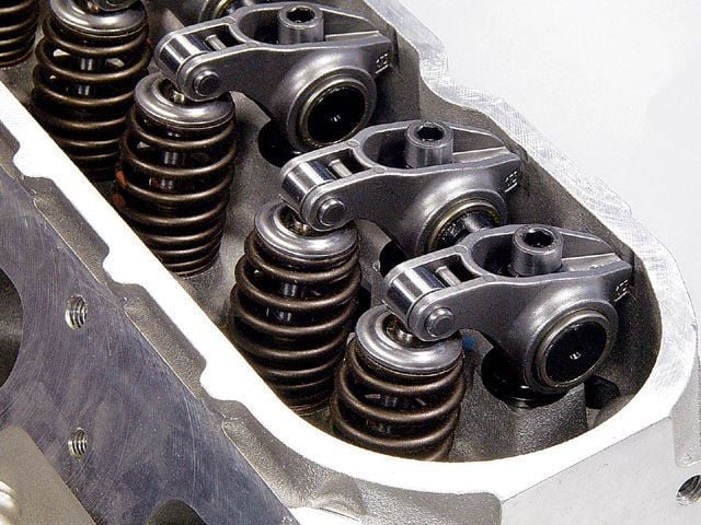
In an application such as a Super Cup Stock Car engine, valve lofting requires that valvetrain components be robust enough to “survive the beating”, as Brown describes it. “Most of the people doing aggressive, controlled lofting tend to have heavier valves. That’s partly because more mass will throw more easily – it will keep going [beyond the nominal maximum lift] a little better – but at the same time the valve must withstand hitting the seat, hard. You also tend to see bulky, steel rocker arms. These days, shaft-mount rocker arms don’t break often, but when they do, it’ll be in one of those situations.
The SpinTron is a great way for engine builders to try out different component options to handle the demands of valve loft. When SpinTrons were first used, they were a factor in convincing builders to move away from the traditional mantra that lighter was always better in a valvetrain.
Pushrods, for example, have continued to increase in size. Brown favors greater outer diameters and thinner walls, to take the component’s natural frequency much higher than the driving frequency on the side of rocker arm where physics dictates that the effective mass of the components is less important. SpinTron tests have also contributed to the deployment of stiffer and lighter valve springs as a means of curtailing bounce and excessive loft.
“On the SpinTron, it’s easy to try the different options and find the sweet spot,” he says. “If I want to change a pushrod, I just pop the valve cover off, change the pushrod, set the lash and run the test. You can monitor the opening deflection, see how a bigger pushrod reduces the deflection and how the valve will start to move quicker. In five minutes, I have tested two alternatives and have the data in front of me to be able to make a decision on what I want to do.
“By running sweeps of the valve spring installation height – measuring the distance to coil bind at maximum lift – I can also tweak the spring frequency,” he continues. “That times the spring oscillations differently, to get the system to respond in different ways at different engine speeds, which ultimately moves the loft mode to a different rpm.”
Final touches
Once the dynamic tests have led to a promising setup, the SpinTron can also be used for durability testing, running lap simulations to ensure that a particular valvetrain combination will survive a NASCAR race, for example. A version of the SpinTron at Hendrick has a 250-horsepower direct-drive motor that will even spin a fully dressed engine to test for frictional losses.
“Valve bounce has gotten a lot better,” Brown concludes. “In the early days of the SpinTron, that’s all that everyone was trying to solve. Valve bounce was breaking parts and the engine wouldn’t turn the rpm that people needed it to turn. Nowadays, there’s a lot of intentional lofting going on.
“Where the SpinTron can help an engine builder is in putting together multiple camshaft, lash and spring combinations, each one stable but with different timing points and areas under the valve lift curve. Each one can then be run on the dyno to learn more about what that engine likes, because each piston and cylinder head combination is different.”